Laser Thickness Monitor
Accessories
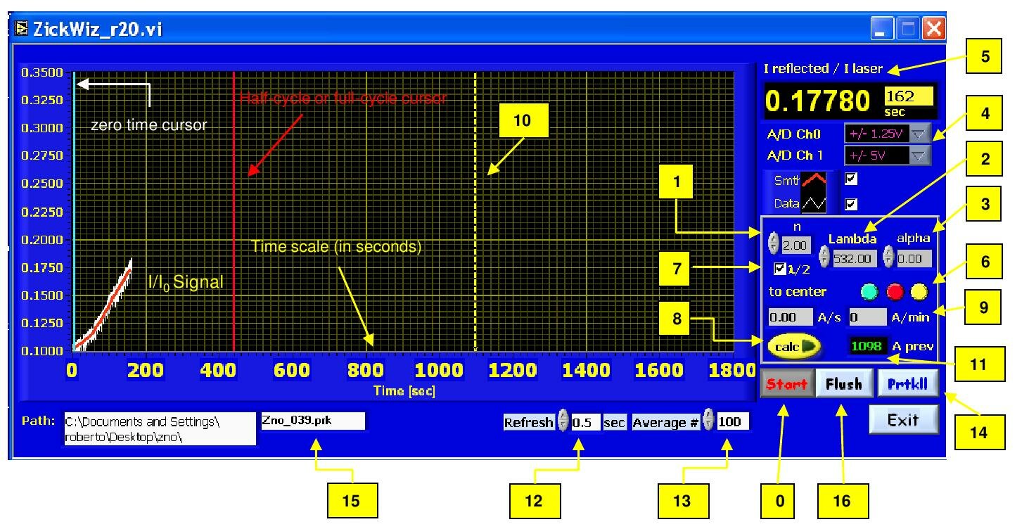
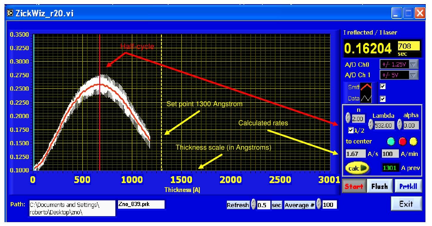
The OS Laser Thickness Monitor (OS-LTM) is designed to perform an in-situ control of thin film growth by a non destructive optical method.
LTM measures the interference pattern intensity during film growth as a function of the elapsed deposition time. The laser intensity is measured by a separate detector in order to compensate for laser intensity fluctuations.
The reflected intensity, which is modulated by interference between the top and the bottom interface of the thin film, depends on the thickness of the growing film on the substrate.
In fact, while the reflection from the substrate is constant, the variation is due to interference of the two interfaces (substrate/sample and sample/vacuum).
The signal depends on the refractive index of the sample and, in turn, on the laser wavelength (lambda) and eventually on the refractive index of the material (n).
It also depends on the laser beam incidence angle with respect to the normal of the sample plane (alpha).
Download the LTM Demo (6.3 MB)
Characteristics
| Operation | remote and in situ | |
|---|---|---|
| Laser wavelength (nm) | 532 (standard) | 405, 632.8 |
| Port Mount | UHV DN40CF (standard) | other mountings on demand |
| Sensitivity (nm) | up to a few nm (for n = 2) | depending on the refractive index (n) |
| Operating System for measuring Software |
Windows XP or more recent | desktop PC with a PCI slot* |
* An RF noise shielded PC is recommended for the use in connection with a PPD System.
Compared to ordinary thickness monitors (i.e. quartz balance thickness monitors) the OS LTM provides the following advantages:
- in–situ measurement system
- real optical thickness measurement during film growth
- installation outside the vacuum chamber
- insensitive to electromagnetic radiation (plasma, RF noise, etc.)
- extremely sensitive to thickness growth (depending on the refractive index; few nm for n=2).
- can be set at any distance from the film (remote)
- no part substitution required.
The features are:
- Excellent stability due to the dual beam detection
- Fully proprietary control system software
- Available with different laser wavelength for refractive response optimization
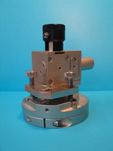
The actual OS LTM is shown on the front page and below are the technical drawings ( Figure 2).
The OS LTM may be fitted directly onto a CF UHV flange glass window provided by AR coating. OS may provide the window as an option.
Other mounting is possible upon demand. An optical adjustment allows perpendicular positioning against the substrate surface by means of a optical Kelvin mount.
The OS LTM can be set at any distance from the film to be measured.
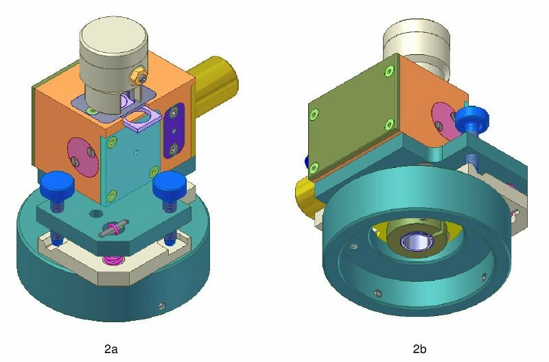
The laser intensity detector is at the top. A side port on the detector cabinet allows to align the reflected beam on the detector.
The system may be quickly detached from the vacuum system.